ESP32S3 A4988 ステッパモータ駆動
モータ指令値に応じた周波数のパルス列を生成するC++クラス
ESP32のPWM信号発生機構利用
2026.7.6 2025.7.20 Coskx Lab
1 はじめに
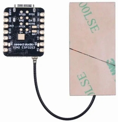
Xiao ESP32S3で小型ステッパモータ(ステッピングモータ)を制御します。
モータ指令値に応じた周波数のパルス列を生成するクラスをC++で作成しました。
このクラスの初期化時点で,指令周波数(モータ指令値が与えられる周波数,例えば200Hz)と最短パルス周期長(例えば20μsec)を与え,
その後,一定周期(200Hzの場合は5msec)でモータ指令値が与えられることを想定しています。
PWM信号の発生はマイコンの持っているPWM発生機構を用いています。
パルス列生成クラスで発生したパルス列で,ステッパモータドライバIC A4988を使用して,小型ステッパモータを駆動します。
小型ステッパモータはパルス列の周波数が高すぎる(パルス周期が短すぎる)と追随できなくなるため,最短パルス周期長を指定しておく必要があります。
A4988にのpulse端子にパルス列を与えるとdir端子への入力値(H or L)に応じてステッパモータは決められたステップ角度で正回転あるいは逆転します。
原理的な説明は次のWebページを参照してください。
≫ モータドライバA4988でステッピングモータ制御
1/16マイクロステップ駆動を採用します。そのため,通常のモータ1ステップ動作は1.8度の回転ですが,ここでは0.1125度(=1.8度の1/16)回転になります。
参考 モータドライバIC A4988基板実装(秋月電子販売など)
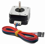
参考 使用しているモータ
名称: 3DプリンターTitan Stepper Motor (AMAZON)
モーターサイズ(L * W * H):42 * 42 * 23 mm
フェーズ:2フェーズ
電圧:4.1V
電流:1A /相
抵抗値:4.1±10%Ω/相
インダクタンス:4.1±20%mH /相
保持トルク:13N.cm以上(18.5oz.in)
ディテントトッグ:2.0N.cm(2.85oz.in)
絶縁材クラス:B
ステップ角:1.8°±5%
重量:132g
2 使用環境
- Windows 11 64-bit
- Arduino IDE 2.3.10
- Xiao ESP32S3
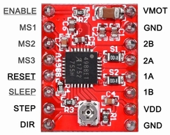
- モータドライバIC A4988
3 実験用配線
次のように配線しました。
DIR端子,STEP端子,ENABLE端子はそれぞれマイコンのD0,D1,D6に接続しました。
1/16マイクロステップ設定のためMS1,MS2,MS3は,3つともH(VDD)に接続します。
RESET端子,SLEEP端子は,それぞれH(VDD),H(VDD)に接続します。
DIR端子はHLの区別でモータを正転逆転の指示を与えます。
STEP端子にパルス信号を与えるごとに,設定された角度(例えば1.8度)だけモータが回転します。
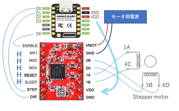
ENABLE端子は通常Lに設定します。
ステッパモータは停まっているときも動いているときも常時電流が流れています。(停まっているときに保持トルクを発生しています。)
ステッパモータを操作していないときで,保持トルク不要の場合は,電流を流さないようにしたいです。そのときは,ENABLE端子にHを与えます。
マイコンの出力端子を一つ使って,プログラムでA4988のENABLE端子にL,H信号を与えるようしています。
なお,モータ用電源は12Vを使いました。
4 電流制限の設定
説明は次のWebページを参照してください。
≫ モータドライバA4988でステッピングモータ制御
5 モータ駆動デモプログラム
モータ駆動の細かなところはパルス生成クラスに任せているので,メイン側の記述は簡素になります。
setup()内では,setPins()でピン割り当てを知らせ,setControlValue()で指令周波数と最短パルス周期長を与えます。
setDirModifier()には通常1を与えます。モータが意図した方向と逆に回ったら,配線を変更することなく-1を与えることで修正できます。
enableDriver()はENABLE端子にLを与えます。
loop()内でdrive()でモータ指令値をパルス生成クラスに与えています。モータ指令値は-1.0から1.0までが有効で,正の値の場合は正転,負の場合は逆転します。
絶対値が大きいほど速く回ります。
駆動パルスは次のような関係になります。
指令値絶対値が小さい パルス間隔が長い パルス周波数が低い
指令値絶対値が大きい パルス間隔が短い パルス周波数が高い
loop()は50msec間隔で起動するようにし(setControlValue()で与えた周波数と一致させる),drive()は50msec間隔で指令値を与えるようにします。
このテストプログラムでは,指令値が変化するのはloop()の200回起動ごとになるため,モータへの指令値が変化するのは,1秒ごとです。
このテストプログラムでの駆動では,モータ指令値を-0.1から0.1で変化させ,ゆっくり回ることを試しています。
パルス発生はクラスStepperMotorESP32で関数ledcWrite()を用いて行われています。この関数は指定した端子ピンに指定した周波数のパルスを連続発生します。
次に関数ledcWrite()が呼び出されるまでパルス発生は継続します。周波数0を指定すると連続パルス発生は停まります。
動作周期と最小パルス間隔の設定によりますが,指令値が非常に小さいとモータが回らないこともあります。
クラスStepperMotorESP32は最初に指示された指令周波数(200Hz)と最小パルス周期(20μsec)から指令周期(5msec)内に詰め込むことのできる最大パルス数を求めています。(MaxControlValue = 250)
モータ指令値(絶対値は0.0から1.0まで)が与えられると,指令周期(5msec)内で発生すべきパルス周波数(モータ指令値に比例した値)を求めてパルス列を生成します。
モータ指令値が1.0の時に最大パルス数になるように,比例計算が行われます。
ArduinoIDEを作業では,クラス定義ファイル(StepperMotorESP32.cpp,StepperMotorESP32.h)を含む次の3つのファイルを同一作業フォルダに入れてください。
3つのファイルは次からダウンロードできます。
3つのファイルのダウンロード
ステッパモータの動作テスト用プログラム本体(メイン)
//steppermotorA4988withclass_singleDEMO.ino
// A4988ステッピングモータードライバーモジュール
#include "StepperMotorESP32.h"
StepperMotorESP32 stepper;
uint32_t MinPulsePeriod = 20; //[microsec]
uint32_t ControlFrequency = 200; //[Hz]
const uint8_t PinDIR = D0;
const uint8_t PinSTEP = D1;
const uint8_t PinEnable = D6; // モータドライブEnable(負論理)に使用する PIN番号
int MaxControlValue;
void setup() {
Serial.begin(115200);
delay(100);
Serial.println("Hello");
stepper.setPins(PinDIR, PinSTEP, PinEnable);
stepper.setDirModifier(1);
MaxControlValue = stepper.setControlValue(ControlFrequency, MinPulsePeriod);
Serial.print("MaxControlValue = ");
Serial.println(MaxControlValue);
stepper.enableDriver();
}
void loop() {
static int control = 0;
static int dcontrol = 1;
static int n=0;
int res;
double fcontrol = (double)control/50.;
res = stepper.drive(fcontrol);
n++;
if (n == ControlFrequency) {
if (control == 5 || control == -5) {
dcontrol *= -1;
}
control += dcontrol;
n=0;
Serial.print("control, res = ");
Serial.print(fcontrol);
Serial.print(", ");
Serial.println(res);
}
delay(1000/ControlFrequency); //[msec]
}
6 実行の様子
小さな指令値(指令値受容範囲が-1.0から1.0に対して,-0.1から0.1の範囲での指令値を使用)を使っているためゆっくりとモータは回転します。
次のようなログが得られました。
MaxControlValue = 250 となっているので,指令周期内(5msec)内に生成されるパルス数は0から250になります。
-0.1から0.1の範囲での指令値で,指令周期内(5msec)内に0から25個のパルスを連続発生している様子がわかります。
Hello
MaxControlValue = 250
control, res = 0.00, 0
control, res = 0.02, 5
control, res = 0.04, 10
control, res = 0.06, 15
control, res = 0.08, 20
control, res = 0.10, 25
control, res = 0.08, 20
control, res = 0.06, 15
control, res = 0.04, 10
control, res = 0.02, 5
control, res = 0.00, 0
control, res = -0.02, -5
control, res = -0.04, -10
control, res = -0.06, -15
control, res = -0.08, -20
control, res = -0.10, -25
control, res = -0.08, -20
control, res = -0.06, -15
control, res = -0.04, -10
control, res = -0.02, -5
control, res = 0.00, 0
control, res = 0.02, 5
control, res = 0.04, 10
control, res = 0.06, 15
control, res = 0.08, 20
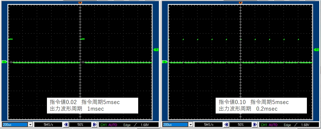
指令値が0.02のときと,0.1のときの出力波形は次のようになりました。
7 考察(1)
ケース1
最小パルス周期と指令周波数が次のように設定されている場合を考えます。
uint32_t MinPulsePeriod = 20; //[microsec]
uint32_t ControlFrequency = 200; //[Hz]
とすると
指令周期(5msec)=1000/ControlFrequency
なので,指令周期(5000μsec)を持つ時間ユニット内に詰め込むことのできるパルス数はMaxControlValue=250になります。(5000/20=250)
指令値とパルス周波数の関係は,比例関係になっています。
モータ指令値(絶対値)に対するパルス周波数の関係をまとめると,次の表のようになります。
ただし,システムクロック周波数 80000000.0Hz(80MHz)からパルスが作られ,パルス発生に使うビット数は9にしているため,
システムが発生することのできるパルス周波数は76.29394531Hzの整数倍になっています。
そのため,実際の「パルス数/5msec」の値は整数でも丸め計算も含むため,1程度の誤差があります。
| モータ指令値 | パルス数/5msec | パルス周期[μsec] | パルス周波数[Hz] |
| 1.0 | 249 | 20.01 | 49972 |
| 0.9 | 224 | 22.25 | 44937 |
| 0.8 | 199 | 25.01 | 39978 |
| 0.7 | 174 | 28.61 | 34942 |
| 0.6 | 149 | 33.35 | 29983 |
| 0.5 | 124 | 40.08 | 24948 |
| 0.4 | 99 | 50.02 | 19989 |
| 0.3 | 74 | 66.87 | 14953 |
| 0.2 | 49 | 100.0 | 9994.5 |
| 0.1 | 24 | 201.6 | 4959.1 |
| 0.05 | 12 | 409.6 | 2441.4 |
| 0.02 | 4 | 1008 | 991.82 |
| 0.01 | 2 | 2184 | 457.76 |
| 0.005 | 1 | 4369 | 228.88 |
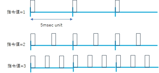
モータ指令値が与えられる指令周波数が200Hzのとき,次の図のような指令周期(5msec)の時間ユニットになります。
この時間ユニットが連続して生成されます。
時間ユニット中に綺麗にパルスを並べるため生成されるためパルス周期は離散的になります。
モータ指令値が0.01くらいになって,パルス数/5msecが1前後になると,この縛りのため,
パルス周期3.5msecのようなパルスは生成できません。
ケース2
ケース1の設定では生成パルス周波数が高すぎるように思いました。
そこで最小パルス周期と指令周波数が次のように設定されている場合を考えます。
uint32_t MinPulsePeriod = 60; //[microsec]
uint32_t ControlFrequency = 100; //[Hz]
とすると
指令周期(10msec)=1000/ControlFrequency
なので,指令周期(10000μsec)を持つ時間ユニット内に詰め込むことのできるパルス数はMaxControlValue=166になります。(10000/60=166.7)
指令値とパルス周波数の関係は,比例関係になっています。
モータ指令値(絶対値)に対するパルス周波数の関係をまとめると,次の表のようになります。
ただし,システムクロック周波数 80000000.0Hz(80MHz)からパルスが作られ,パルス発生に使うビット数は9にしているため,
システムが発生することのできるパルス周波数は76.29394531Hzの整数倍になっています。
そのため,実際の「パルス数/10msec」の値は整数でも丸め計算も含むため,1程度の誤差があります。
| モータ指令値 | パルス数/10msec | パルス周期[μsec] | パルス周波数[Hz] |
| 1.0 | 166 | 60.124 | 16632.0 |
| 0.9 | 149 | 66.873 | 14953.6 |
| 0.8 | 132 | 75.328 | 13275.1 |
| 0.7 | 115 | 86.231 | 11596.6 |
| 0.6 | 99 | 100.05 | 9994.50 |
| 0.5 | 83 | 120.24 | 8316.04 |
| 0.4 | 66 | 150.65 | 6637.57 |
| 0.3 | 49 | 201.64 | 4959.10 |
| 0.2 | 32 | 304.81 | 3280.63 |
| 0.1 | 16 | 624.15 | 1602.17 |
| 0.05 | 7 | 1310.7 | 762.939 |
| 0.02 | 3 | 3276.8 | 305.175 |
| 0.01 | 1 | 6553.6 | 152.587 |
| 0.005 | 0 | 13107 | 76.2939 |
8 考察(2)
クラスStepperMotorESP32ではPWM信号発生にAPI ledcを使用しています。
PWM周波数切り替え時に,関数ledcChangeFrequency()を使用しています。
この関数はPWM周波数切り替え時に初期化PWM信号発生機構を初期化してしまい,およそ,340μsecだけPWM信号をLにしてしまいます。
100Hzくらいの頻度で関数ledcChangeFrequency()を実行すると,意図したPWM信号とは少し異なるパルスが発生します。
頻繁にPWM周波数切り替える用途には向かないステッパモータ駆動法と考えられます。
詳細は次を参照してください。
Xiao ESP32S3 でPWM信号発生テスト ≫
9 まとめ
Xiao ESP32S3およびモータドライバA4988でステッパモータを駆動しました。
駆動ではあらかじめ指定した指令周期ごとにモータ指令値を変更するパルス生成クラスを用いて,プログラミングの負担を減らしています。
ここで使用しているパルス生成クラスでのPWM信号発生は,マイコンの持っているPWM発生機構を用いています。
指令周期の時間ユニット内には整数個のパルスしかおけず,2.5個のような値は取れません。
そのため,低い周波数のパルス周波数が離散的になってしまい,制御のスムースさが損なわれるかもしれません。
ここでの指令周期は5msec(指令周波数 ControlFrequency = 200 [Hz])でしたが,
指令周期を20msec(50[Hz])あるいは100msec(10[Hz])にするとこの欠点は緩和されると思われます。
また最小パルス発生周期を20μsecと設定していますが,ステッパモータの特性を考えるとそこまで短くする必要はないかもしれません。
60μsec程度で十分と思えます。
★重要 このデモプログラムではステッパモータ向けのパルス信号をESP32のAPI Ledcを用いて生成しています。
「8 考察(2)」の問題点を考慮して,頻繁なPWMパルス周波数変更があるような用途にAPI ledcを使用した本ページ記述の方法は避けるべきと考えます。